
EnWater Design

FlowPlan  ›  Process Mapping

Process Mapping

Process Mapping defines how the selected treatment stages function as one system. We map feed, product, recycle, reject and residual streams; confirm storage, equalisation and connection points; and set the control, monitoring and operating logic needed before detailed design and supplier engagement.

Stream mapping Flows & loads Connections & recycles Controls & verification

The map is developed against the design basis, site constraints, operator context and required performance, with normal, standby, cleaning and abnormal operating conditions considered.

Connected process basis, defined before delivery

The mapped systems show how treatment stages, internal returns, utilities, controls and residuals connect, so detailed design and supplier scope can proceed from a common process basis.

  • We map feed, product, recycle, reject and residual streams through the selected treatment stages.
  • We define storage, bypasses, recycles, chemical, air and heat connections, and monitoring points.
  • We confirm operating modes, site constraints and verification requirements before handover to Planning & Delivery.

What the process map confirms

Stage duties & performance criteria: required inputs, outputs, operating ranges and monitoring points defined for each stage.
Connections & constraints: hydraulic, chemical, air, heat, drain and residual connections checked against space, utilities and operating limits.
Verification focus: monitoring, alarms, sampling and acceptance requirements defined for later Planning & Delivery.

Mapped systems for reuse, recovery and residuals

Each system review starts from the selected treatment stages and maps how feed, product, recycle, reject and residual streams move between them. Storage, bypasses, utilities, controls and verification points are defined against site conditions and end-use obligations before detailed design proceeds.

Each engagement builds from the confirmed design basis and selected treatment stages. Process Mapping then defines stream connections, operating conditions, controls, monitoring points and handover requirements for detailed design and Planning & Delivery.

Module reference: connections within the mapped system

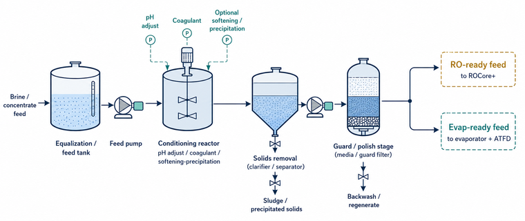
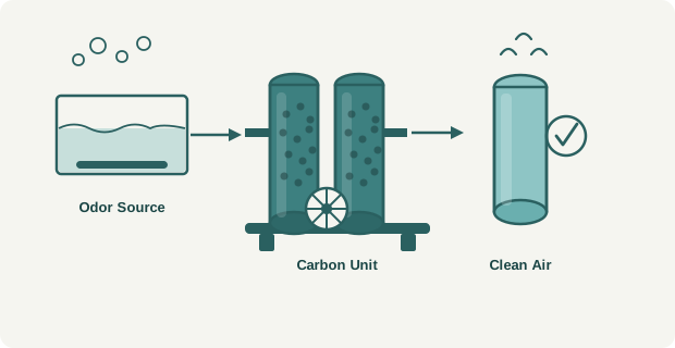
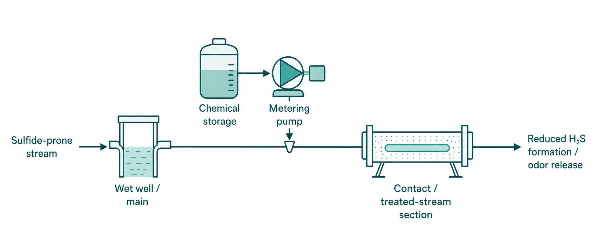
Each module represents a process stage or operation within the selected system. The reference review shows its required duty, position, upstream and downstream connections, side streams, controls and verification points so the complete map can be checked before supplier engagement.

22

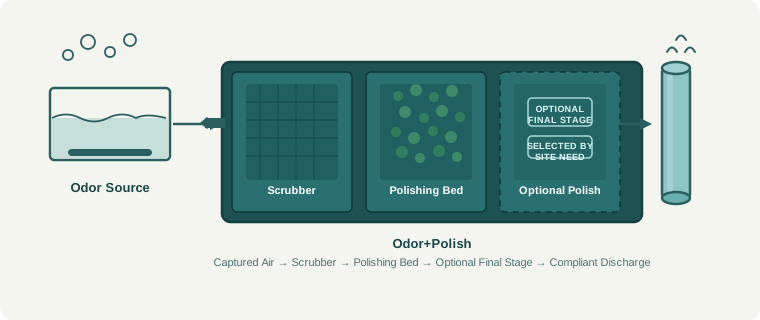
Odor+Polish

Selected final air-polishing route for captured air streams, using one chosen polishing method based on inlet load, site constraints and discharge needs.

PolishAir
MBBR+
Clari+ - Disc
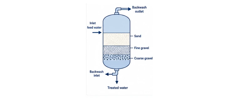
Clari+ - PSF
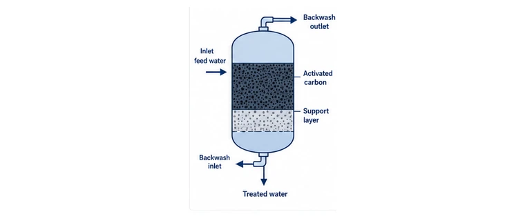
Clari+ - Activated Carbon
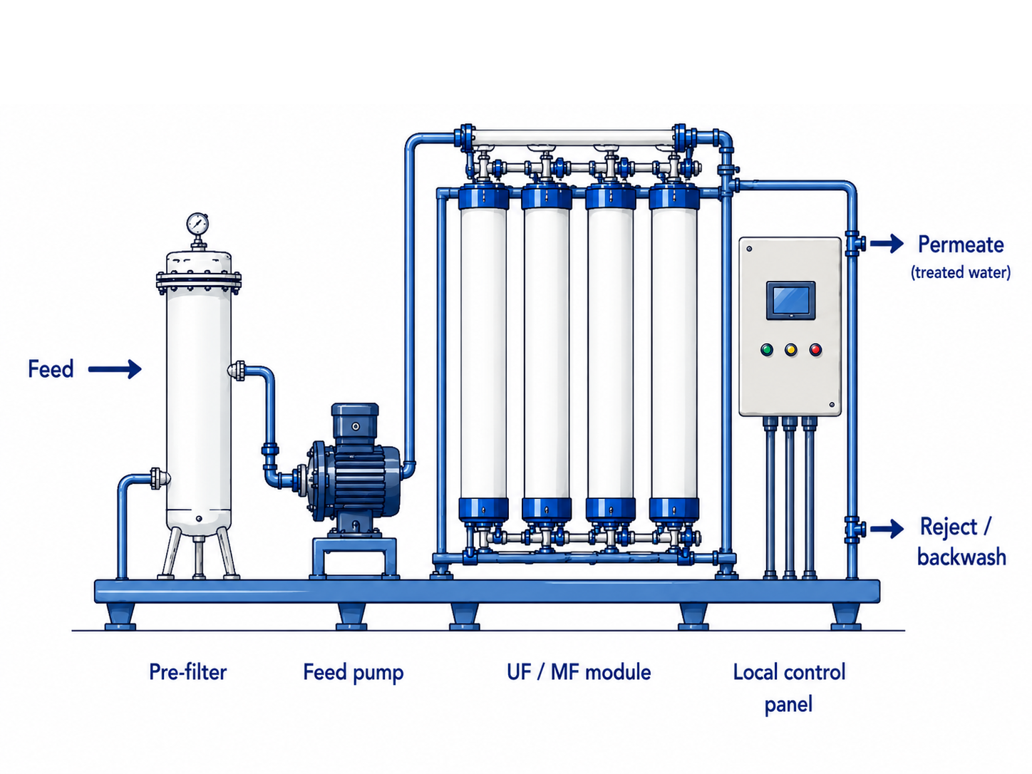
Micra+ - UF/MF
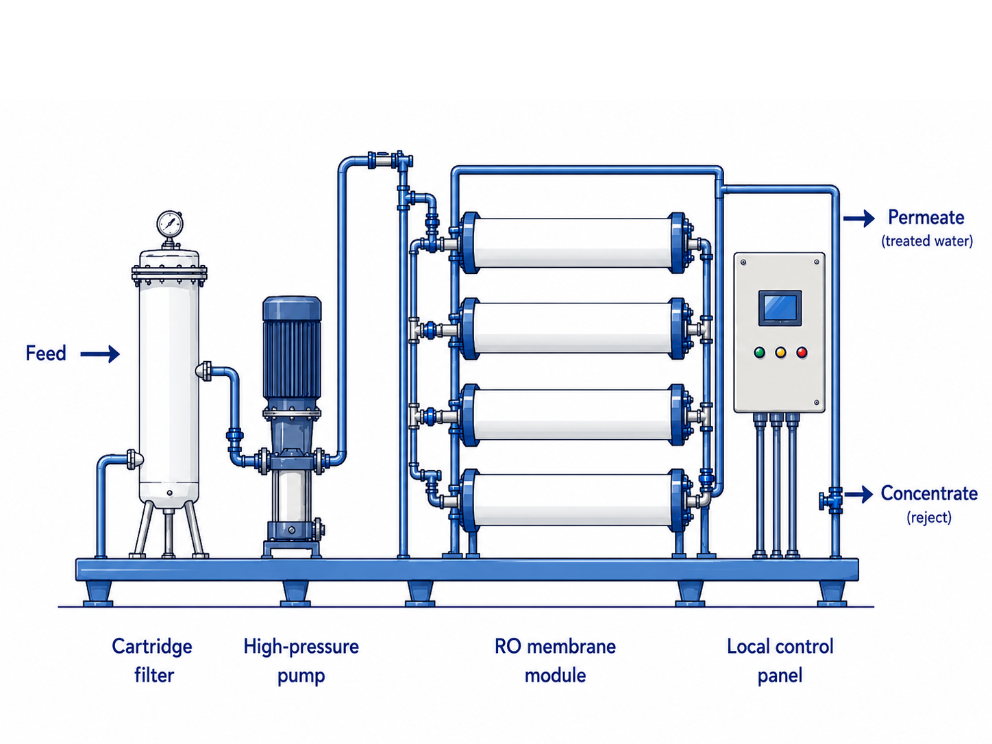
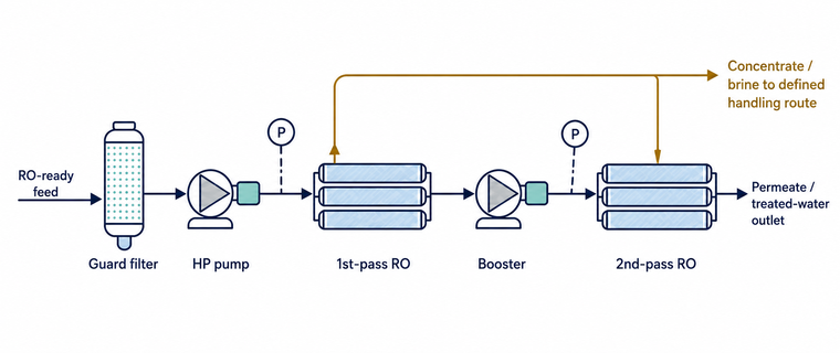
MicraRO+
ROCore+
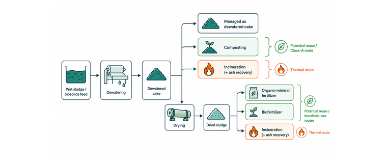
Sludge+
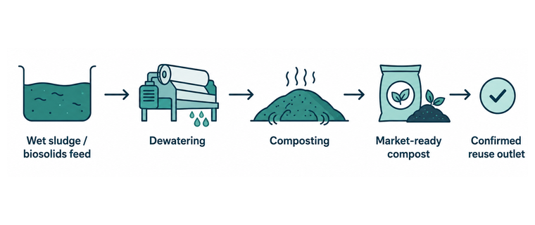
Sludge+Compost - Compost
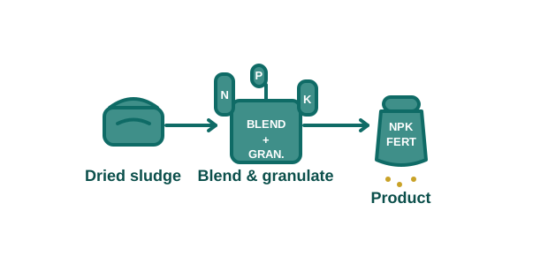
Sludge+Fert - Organo-mineral fertilizer
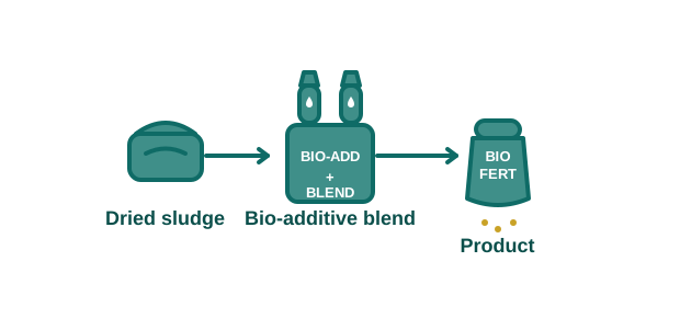
Sludge+Bio - Biofertilizer
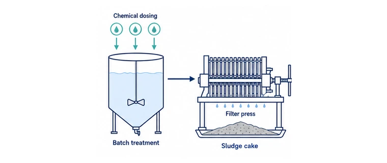
Batch+
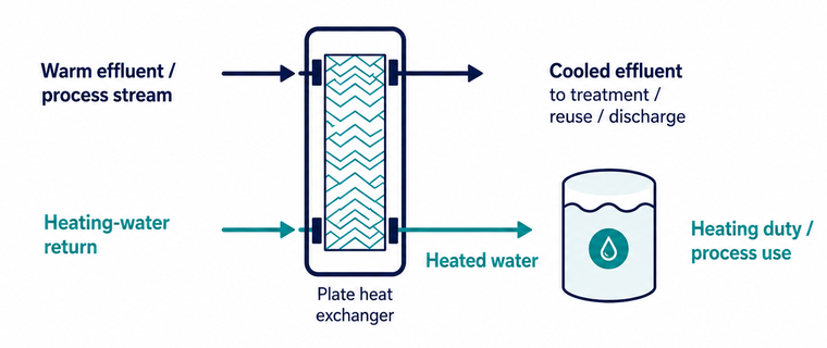
Thermo+Heating Loop
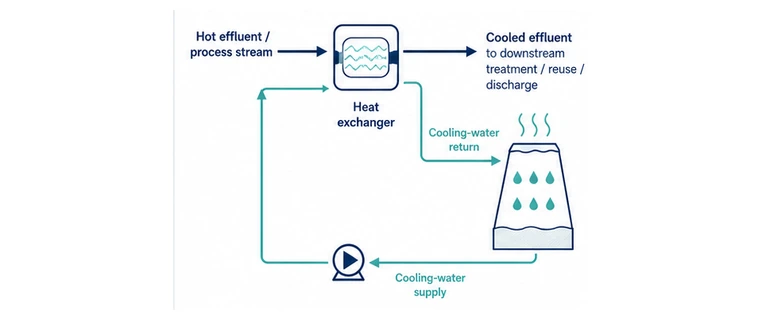
Thermo+Cooling Loop
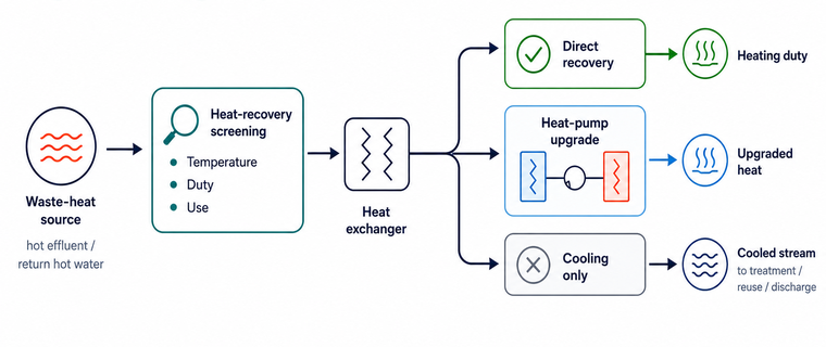
Thermo+Heat Recovery Screening
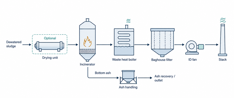
Incineration+
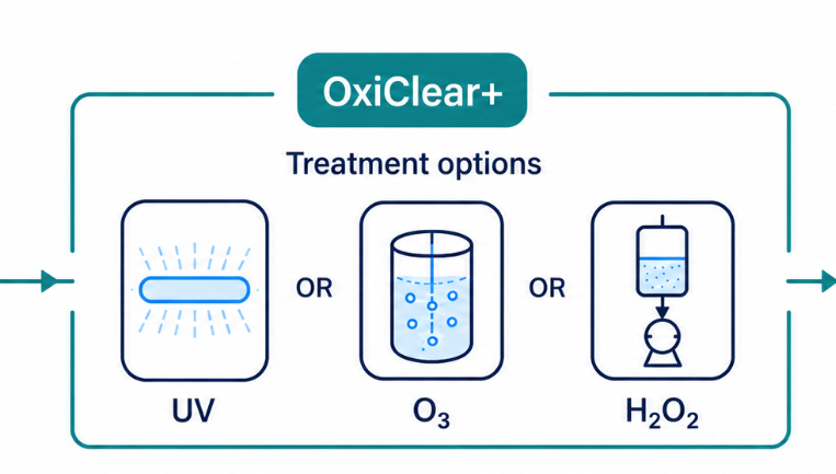
OxiClear+
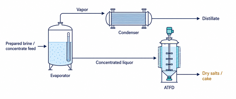
ZLD Prep +
ZLD+
Odor+Capture
Odor+Dose
Odor+Polish
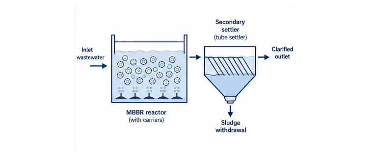
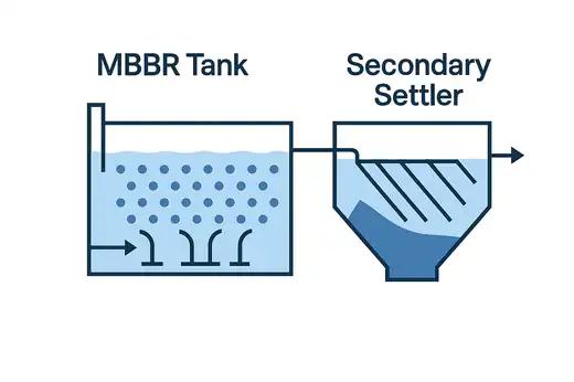
MBBR+
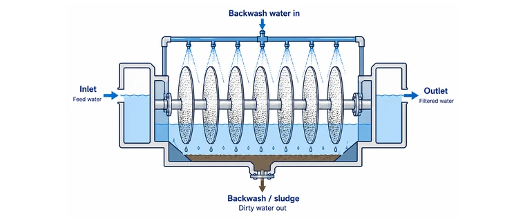
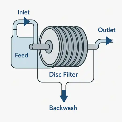
Clari+ - Disc

What Process Mapping defines

The review follows the system stage by stage, defining what each stage receives, what it produces, how side streams and utilities connect, and how the system operates under normal, standby, cleaning and abnormal conditions.

What the map covers

  • Where each selected stage belongs in the system and how feed, product, recycle, reject and residual streams connect.
  • What each stage requires: flow and load range, storage, utilities, operating modes, controls, monitoring and maintenance access.
  • What must be passed into detailed design and Planning & Delivery so supplier scope is based on a common process basis.

Related inputs and next steps

These focused reviews either supply information needed for the process map or use its outputs in later evaluation and delivery work.

Focus area

Vendor / Technology Evaluation

Uses the completed process map to set common connection, performance and OPEX questions for proposal comparison.

Focus area

Plant Health Check

Provides operating data, load observations and connection constraints where the existing system must be understood before mapping changes.

Focus area

Trade Effluent Pretreatment

Defines source segregation, equalisation, pretreatment and monitoring inputs needed to protect the mapped downstream system.

Focus area

Biosolids Planning

Provides the material, QA and outlet basis needed before sludge and residual connections are finalised in the process map.

Get in touch

Share the selected treatment stages, design basis and site context. We map the streams, connections, operating modes, controls and verification points needed before detailed design and supplier engagement.

  • The end-use outcome you’re targeting (cooling, irrigation, process reuse, discharge risk reduction, brine management, residuals & biosolids).
  • Feed and operating context (flows/loads, variability, salinity/chemistry, existing operating problems and current assets).
  • Practical constraints (space, utilities/heat, shutdown periods, operator capacity, connection points).
  • Where you want clarity (stream routing, storage, recycles, bypasses, utilities, control points, monitoring and handover requirements).
  • Available inputs (recent sampling, monitoring logs, drawings, O&M history), and what’s missing.
Open enquiry form

Share your outcome objective and we will come back with the right approach.

Outcome treatment scheme